|
|
|
Who's Online
There currently are 5643 guests and
3 members online. |
|
Categories
|
|
Information
|
|
Featured Product
|
|
|
 |
|
|
There are currently no product reviews.
 ;
The owners manual for the Pioneer VSX-D603S was exactly what I needed. I received it in a timely manor and it was priced fairly. I definately will use your servise again. Thank You
;
This is a great manual. It was easy to read and very accurate. The size of the manual is small so email is no problem. I highly recommend it. The manual is very hard to find other than this website.
;
Manual was complete and available promptly, since I had lost my original manual. Very good response.
;
Whilst this is a photo copy, and some of the pages are a little askew, it was all readable and intact. A real bonus finding an old manual for a classic piece of kit that no other site had.
Great stuff.
;
excellent quality, contains circuits and scan quality, 110 pages
With Iron Wire: 1. Using desoldering braid, remove the solder from all pins of the flat pack-IC. When you use solder flux which is applied to all pins of the flat pack-IC, you can remove it easily. (Fig. S-1-3) 2. Affix the wire to a workbench or solid mounting point, as shown in Fig. S-1-5. 3. While heating the pins using a fine tip soldering iron or hot air blower, pull up the wire as the solder melts so as to lift the IC leads from the CBA contact pads as shown in Fig. S-1-5. 4. Bottom of the flat pack-IC is fixed with glue to the CBA; when removing entire flat pack-IC, first apply soldering iron to center of the flat pack-IC and heat up. Then remove (glue will be melted). (Fig. S-1-6) 5. Release the flat pack-IC from the CBA using tweezers. (Fig. S-1-6) Note: When using a soldering iron, care must be taken to ensure that the flat pack-IC is not being held by glue. When the flat pack-IC is removed from the CBA, handle it gently because it may be damaged if force is applied.
2. Installation
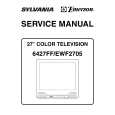
1. Using desoldering braid, remove the solder from the foil of each pin of the flat pack-IC on the CBA so you can install a replacement flat pack-IC more easily. 2. The ��� mark on the flat pack-IC indicates pin 1. (See Fig. S-1-7.) Be sure this mark matches the 1 on the PCB when positioning for installation. Then presolder the four corners of the flat pack-IC. (See Fig. S-1-8.) 3. Solder all pins of the flat pack-IC. Be sure that none of the pins have solder bridges.
Example :
Hot Air Blower
Pin 1 of the Flat Pack-IC is indicated by a " " mark.
Fig. S-1-7
or Iron Wire
Presolder
Soldering Iron To Solid Mounting Point Fig. S-1-5 Flat Pack-IC CBA CBA Fine Tip Soldering Iron Fig. S-1-8
Flat Pack-IC Tweezers Fig. S-1-6
3-3
TVN_SN
|
|
|
> |
|