|
|
|
Who's Online
There currently are 5578 guests online. |
|
Categories
|
|
Information
|
|
Featured Product
|
|
|
 |
|
|
There are currently no product reviews.
 ;
I love older radio's and the service manuals that are sometimes hard to find. Was able to find a manual quite easily on this site.
;
Thank you for your shop manual! Your help was very useful - the device is repaired! Once again - Thank you! I wish you a successful business! Edward (Russia).
;
It was a great experience,instead of purchasing a new Stereo Amplifier ,in just minutes i repaired my old one and that was thaks to the manual I have purchased from you.
Thanks again.
Samuel Alter
;
Das ging ja sehr unkompliziert hat bestens geklappt und die Quallität ist auch noch gut.
Vielen Dank dafür.
;
Everything okay, thanks a lot. It was a pleasure for me to make a deal with you.
6. Press CH DOWN button on the unit until the CTL waveform has shifted from its original position (not the position achieved in step 5, but the position of CTL waveform in step 4) by approximately -2msec. Make sure that the envelope is simply attenuated (shrinks in height) once CTL waveform passes its original position and is further brought in the minus direction. 7. Set the Tracking Control Circuit to the center position by pressing CH UP button and then � PLAY � button.
1-D. Azimuth Alignment of Audio/Control/ Erase Head
Purpose: To correct the Azimuth alignment so that the Audio/ Control/Erase Head meets tape tracks properly. Symptom of Misalignment: If the position of the Audio/Control/Erase Head is not properly aligned, the Audio S/N Ratio or Frequency Response will be poor. 1. Connect the oscilloscope to the audio output jack on the rear side of the deck. 2. Playback the alignment tape (FL8NW) and confirm that the audio signal output level is 8kHz. 3. Adjust Azimuth Adj. Screw so that the output level on the AC Voltmeter or the waveform on the oscilloscope is at maximum. (Fig. M6) Dropping envelope level at the beginning of track.
1-C. Checking/Adjustment of Envelope Waveform
Purpose: To achieve a satisfactory picture and precise tracking. Symptom of Misalignment: If the envelope output is poor, noise will appear in the picture. The tracking will then lose precision and the playback picture will be distorted by any slight variation of the Tracking Control Circuit. 1. Connect the oscilloscope to TP301 (C-PB) on the Main CBA. Use TP302 (RF-SW) as a trigger. 2. Playback the Gray Scale on the Alignment Tape (FL8NW). Set the Tracking Control Circuit to the center position by pressing CH UP button and then � PLAY � button on the unit. Adjust the height of Guide Rollers [2] and [3] (Fig. M3, Page 2-3-3) watching the oscilloscope display so that the envelope becomes as flat as possible. To do this adjustment, turn the top of the Guide Roller with the Guide Roller Adj. Screwdriver. 3. If the envelope is as shown in Fig. M7, adjust the height of Guide Roller [2] (Refer to Fig. M3) so that the waveform looks like the one shown in Fig. M9. 4. If the envelope is as shown in Fig. M8, adjust the height of Guide Roller [3] (Refer to Fig. M3) so that the waveform looks like the one shown in Fig. M9. 5. When Guide Rollers [2] and [3] (Refer to Fig.M3) are aligned properly, there is no envelope drop either at the beginning or end of track as shown in Fig. M9. Note: Upon completion of the adjustment of Guide Rollers [2] and [3] (Refer to Fig. M3), check the X Value by pushing the CH UP or DOWN buttons alternately, to check the symmetry of the envelope. Check the number of pushes to ensure center position. The number of pushes CH UP button to achieve 1/2 level of envelope should match the number of pushes CH DOWN button from center. If required, redo the �X Value Alignment.�
Fig. M7 Dropping envelope level at the end of track.
Fig. M8 Envelope is adjusted properly. (No envelope drop)
Fig. M9
2-3-4
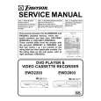
U27NMA
|
|
|
> |
|